The well-known osgUtil::LineIntersector helps to find intersections with different osg::Drawables such as QUAD, LINES, and even POINTS. But what if we want to know an intersection point with a virtual object that does not necessary have an osg::Drawable representation?
In this tutorial we will show how to do it by intersecting a mouse ray with a virtual plane data type. The point of intersection, depending on the mouse event, will indicate either a beginning of a line segment, or its end. In simpler words, this tutorial is going to show how to draw line segments on virtual plane using osgGA::EventQueue method, and without using the standard osgUtil::LineIntersector.
As mentioned above, we will also have to take into account a mouse event type. When mouse is pressed, it will indicate the beginning of the line segment. When mouse is dragged, we shall be able to see the temporal position of the segment’s end. Finally, when mouse is realised, it will indicate the definite end of the segment.
Before we start talking about ray casting, we have to define some helper classes:
Canvas to represent a virtual plane in 3D spaceStroke to represent a line segment within CanvasCanvasFor simplicity, we are going to call our custom virtual plane as canvas. This name reflects its purpose much better since one of its main functions is to maintain line segments that user draws in 3D space.
We are going to describe the canvas plane by point-normal form. A plane can be expressed as a set of points \(P\) for which
\[(P-C)\vec{n} = 0\]
Where \(\vec{n}\) is a normal vector to the plane, and \(C\) is a point on the plane. For canvas, we define point \(C\) to be a center of the plane which is chosen arbitrary (for our coding example we use coordinates \(C=[0,0,0]\)).
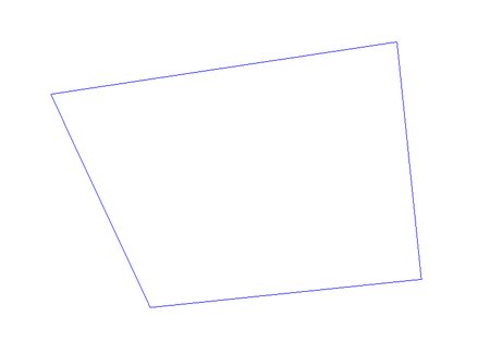
Now we have to think of a graphical representation for our class. It would be useful to have some type of visual reference for the user that helps to make more sense about the location of the canvas. We represent our canvas as a rectangle, which is defined as four points that lie within the plane, and four lines that connect those points so that a rectangle is formed.
We choose constant coordinates for the four points (vertices) which are spread around the arbitrary center \(C\).
The figure below is an example of the canvas representation:
The canvas class implementation consist of the next elements:
osg::MatrixTransform.Here is en example of the canvas API:
class Canvas : public osg::Group
{
public:
    Canvas();

    void addStroke(Stroke* stroke);
    const Stroke* getStroke(unsigned int i) const;
    void doStroke(float u, float v, int mouse);

    const osg::Vec3& getCenter() const;
    osg::Plane getPlane() const;
    osg::MatrixTransform* getTransform() const;

protected:
    ~Canvas();

private:
    osg::ref_ptr<osg::MatrixTransform> m_transform;
    osg::ref_ptr<osg::Geode> m_dataGeode;
    osg::ref_ptr<entity::Stroke> m_stroke;

    osg::Vec3 m_center;
    osg::Vec3 m_normal;
};
For the class implementation details, refer to the corresponding tutorial file (link provided at the end of this tutorial).
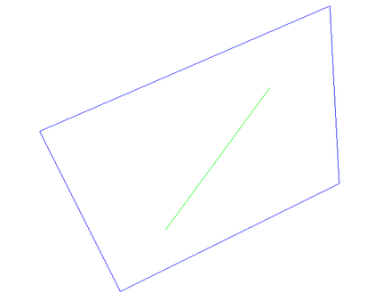
StrokeThe line segment type is called a Stroke. The stroke is represented by two points that lie within our canvas and which are connected by a line segment.
The vector equation for a line is
\[P = x\vec{d} + d_0\]
Where \(\vec{d}\) is the direction of the line segment, \(d_0\) - is a point on the line, and \(x\) is a scalar in the real number domain.
We want to be able to set stroke’s properties such as start coordiate, end coordinate and color. The API looks like following:
class Stroke : public osg::Geometry
{
public:
    Stroke();

    void setColor(const osg::Vec4& c);
    void setBegin(float a, float b);
    void setEnd(float c, float d);
    void setBeginEnd(float a, float b, float c, float d);
protected:
    ~Stroke();
};
When the stroke is drawn on the canvas, it lies within the canvas’ virtual plane:
In order to incorporate the ray casting procedure into the standard OSG event handler, we have to re-implement its osgGA::GUIEventAdapter class. For that class, we need to re-define bool handle() method which we will use to include the event processing for ray casting.
The minimal API for the re-defined event handler looks like following:
class EventHandler : public osgGA::GUIEventHandler
{
public:
    EventHandler(entity::Canvas* canvas);
    virtual bool handle(const osgGA::GUIEventAdapter& ea, osgGA::GUIActionAdapter& aa);

    virtual void doStroke(double u, double v, int mouse);

protected:
    bool getRaytraceCanvasIntersection(const osgGA::GUIEventAdapter& ea,
                                       osgGA::GUIActionAdapter& aa,
                                       double& u, double& v);

private:
    osg::observer_ptr<entity::Canvas> m_canvas;
};
For the stroke drawing procedure, we introduced a variable mouse which defines what event is dealt with: button pushed, button dragged or button released. mouse (with local coordinates) are passed to the corresponding method within the Canvas class and it helps to define what method to call, e.g., if the button was pressed, it will cause to call a new Stroke constructor, etc.
In this tutorial, we are not going deep into implementation and organization details. The provided codes only cover bare minimum, and might not process all the possible errors and corner cases. Here we will rather concentrate on the ray cast algorithm, and how to implement it within the given framework.
Given the event handler’s API above, we will mainly focus on the content of getRaytraceCanvasIntersection() method. As input, it takes references for event adapter and action adapter and it returns two values: local 2D coordinate of the cast mouse ray.
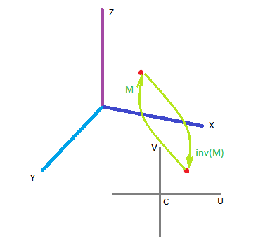
Each canvas has its own local coordinate system. Since the canvas is represented by a plane, and the plane is represented by a center point \(C\) and normal \(\vec{n}\), we place the local coordinate system around plane’s central point \(C\), and that system is two-dimensional. For simplicity, we also orient the local coordinate axes \(\vec{U}\) and \(\vec{V}\) aligned with the global axes \(\vec{X}\) and \(\vec{Z}\).
Consider a stroke that has global coordinate \(P=[X,Y,Z]\) as a beginning point. That coordinate \(P\) can be also represented in canvas’ local 2D system: \(p=[u,v]\) (more precisely, it is \(p=[u,0,v]\), but we omit the \(y\)-coordinate since it is always \(0\)). The relationship between \(P\) and \(p\), or global-model (global-local) projection is given by a canvas transform model matrix \(M\):
\[P = Mp\]
In order to obtain local coordinates \(p\), given the global coordinate \(P\), we need to use the inverse of \(M\):
\[p = M^{-1}P\]
We follow standard steps of the ray cast algorithm:
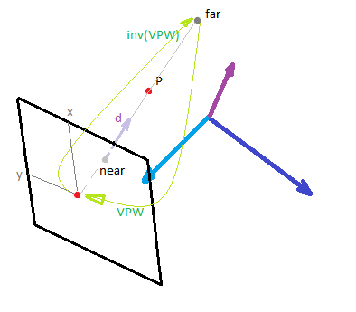
Based on line equation \(P = x\vec{d} + d_0\): when we do the ray casting, we only have to deal with a line segment which is enclosed between far and near points of the mouse ray. The two points are enough in order to get the line variables:
\[\vec{d} = \text{far}-\text{near}\] \[d_0 = \text{near}\]
In order to extract those points from a given screen mouse coordinate \(m=[x,y]\), we have to project point \(m\) into 3D space (which results in a mouse ray, see references for more info on ray tracing).
To obtain screen coordinates of near and far points, we append 0 and 1 as z-coordinate correspondingly:
\[\text{near}_s = [x,y,0]\] \[\text{far}_s = [x,y,1]\]
Where \([x,y]\) are the mouse screen coordinates that we obtain using the passed variable of osgGA::GUIEventAdapter.
Let’s denote any screen coordinate - whether it is far or near - as \(p_s\). To project \(p_s\) into 3D global coordinate system, we have to take an inverse of the matrix that is used to project the global 3D coordinate into the screen one. We call the matrix for direction global - screen as view-projection-window:
\[\text{VPW} = \text{View}\cdot \text{Projection} \cdot \text{Window}\]
Therefore, in order to project back from screen to global, we need to use the inverse:
\[P = \text{(VPW)}^{-1} \cdot p_s^T\]
The above equation is used in order to obtain global coordinates for the near and far points:
\[\text{near} = \text{(VPW)}^{-1} \cdot [x,y,0]^T\] \[\text{far} = \text{(VPW)}^{-1} \cdot [x,y,1]^T\]
Note: we do not have to normalize the coordinates of mouse point \(m\) because we are using OSG window matrix \(W\) which already takes care of normalization.
This is how we use the above formulas in our code:
osg::Matrix VPW = camera->getViewMatrix()
        * camera->getProjectionMatrix()
        * camera->getViewport()->computeWindowMatrix();

osg::Matrix invVPW;
invVPW.invert(VPW);

osg::Vec3f nearPoint = osg::Vec3f(ea.getX(), ea.getY(), 0.f) * invVPW;
osg::Vec3f farPoint = osg::Vec3f(ea.getX(), ea.getY(), 1.f) * invVPW;
Note: the instance ea is of the type osgGA::GUIEventAdapter&; and its methods getX() and getY() return unnormalized mouse screen coordinates.
From the equations of plane and line, we can find a mathematical point of intersection between our ray and corresponding canvas plane. After mathematical simplifications, we obtain the scalar value \(x\) as follows:
\[x = \dfrac{(C-d_0)\cdot \vec{n}}{\vec{d}\cdot \vec{n}}\]
Now it is straightforward to calculate the coordinates of the point of intersection from the line equation:
\[P=\vec{d}x + d_0\]
When performing calculations to find scalar \(x\), we can take advantage of the math methods (dot product) provided by osg::Plane type.
const osg::Plane plane = m_canvas->getPlane();
const osg::Vec3f center = m_canvas->getCenter();

osg::Vec3f dir = farPoint-nearPoint;
double x = plane.dotProductNormal(center-nearPoint) / plane.dotProductNormal(dir);

osg::Vec3f P = dir * x + nearPoint;
Note: we do not consider corner cases in the above code snippet, e.g., when the denominator is zero. Refer to the accompanying code sample for the fully functional code.
To project the global coordinate into a model’s local coordinate, we use an already defined model matrix \(M\). The OSG code for this operation is as follows:
osg::Matrix M = m_canvas->getTransform()->getMatrix();
osg::Matrix invM;
invM.invert(M);

osg::Vec3f p = P * invM;
float u=p.x();
float v=p.z();
Note: the global-local projection transforms 3D coordinates into 2D. While, mathematically, we obtained 3D vector p, the coordinate p.y() is (very close to) zero. We only pass coordinates \([u,v]\) so that to not propagate that close-to-zero y-coordinate. When we create a Stroke within Canvas, we always set y-coordinate manually to zero.
One of the main goals for this tutorial is to accompany a coding example on how to do ray casting using OSG’s event handler. The tutorial is not intended to be concise, but rather cover basic steps and definitions. Consider referring to external references for in-depth explanations on selected subjects.
The main task of the tutorial is to provide mathematical and coding basis for the ray casting technique. The ray casting technique was shown in applied version - drawing line segments by mouse on a virtual plane which is represented by a reference point and normal.
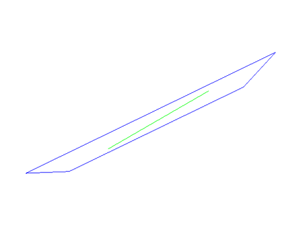
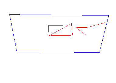
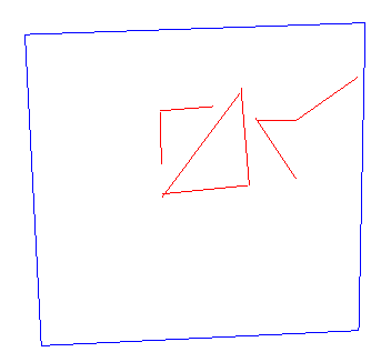
The figures below demonstrate how the output of the coding example looks like. Note, the drawing is done by the right mouse button, while the left button remains to belong to camera manipulator (orbit).
Check a little more complex project example - OSG intersectors, where different types of intersectors are considered (line, point and with the virtual plane through the described ray casting). For the specific tutorial example - check my gist code snippet.
For writing this tutorial, I used several sources. Here I list those I found most useful. There are many other similar resources online, so do not hesitate to do your own research. Some of them relate to OSG event handler, others - are more general about ray tracing, ray casting or event linear algebra.