
How to draw thick and smooth 3D lines in OpenSceneGraph / OpenGL
Context
This tutorial is more expanded version of an answer on my stackoverflow question. To summarize the goal, we want to be able to draw lines in 3D that satisfy the next conditions:
- There is no visible border between the adjacent lines in polyline, which occurs when we use the default OpenGL geometry mode such as
GL_LINE_STRIP_ADJACENCY. - The lines have a 2D look which means the width of lines does not depend on the distance from the camera view. Think of a CAD application and how the lines have the same thickness no matter of their location of viewpoint.
- Possibility to draw lines thicker than allowed default thickness. For example, when I was doing tests on my machine, I could not overcome the thickness of
10.f.
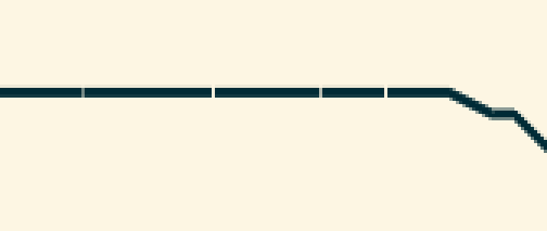
The default OpenGL drawing of line strip geometry does not allow to render smooth (non-broken) lines, as well as to render them of customary thicker than default width:
Main principle
One of the ways to solve the problem is to represent each line segment as a set of triangles. Adjacent triangles (or quads) are drawn without any gaps between them. It is possible to draw those geometries by using GL_TRIANGLE_STRIP. In this case we have to deal with two problems:
- In 3D a set of triangles looks like a ribbon, i.e., it may look like a solid line under certain view, but the line look is lost when the view point is changed.
- The line width depends on the camera view.
To address the problem 1, we have to make sure the geometry is always facing the camera, i.e., recompute the geometries every time the viewpoint is changed. For the problem 2, the solution is similar - re-adjust the ribbon width with the change of viewport.
A very effective way to achieve the desired effect is to use GLSL shaders. Assuming the familiarity of the aforementioned programs, we will move directly to the implementation details.
Implementation details
The presented code is heavily based on the Cinder library discussion thread, and the main principle of triangle coordinates calculation is taken from there as well. In this part I will only provide some details on how to port the shader’s code into OpenSceneGraph program.
Shaders
Here we will provide brief description of each shader.
Vertex shader
The vertex shader is what helps to transform the 3D world coordinates into screen coordinates. Simply speaking, this is where we deal with lines being always faced towards the camera. In order to implement it, we have to use model-view-projection (MVP) matrix which is the matrix that is updated on every view change.
The calculation of each vertex is then done so:
gl_Position = ModelViewProjectionMatrix * Vertex;Geometry shader
The geometry shader’s main goal is to take each line segment (which is represented by lines_adjacency) and turn it into a strip of triangles that have enough filling on each sides so that the consecutive line segment is connected without the gap. The position of each vertex of the triangle is calculated in relation towards the viewport of the widget which displays the whole scene. This allows the lines to have a constant thickness in spite of the their location in 3D world. Refer to the source code for more details on shader implementation.
Fragment shader
The fragment shader is a simple pass-through shader. It takes the incoming color and assigns it to each fragment:
gl_FragColor = VertexData.mColor;For debugging purposes, I set up the color in the shader to green, so that to verify all the previous steps of shader program has completed successfully.
Callbacks
We need to provide two uniforms: for MVP matrix and the Viewport. When using OSG, the best way to do it is by using callbacks. In this case we need to derive from osg::Uniform::Callback. Below are the code snippets for each of the callbacks:
struct ModelViewProjectionMatrixCallback: public osg::Uniform::Callback
{
    ModelViewProjectionMatrixCallback(osg::Camera* camera) :
            _camera(camera) {
    }

    virtual void operator()(osg::Uniform* uniform, osg::NodeVisitor* nv) {
        osg::Matrixd viewMatrix = _camera->getViewMatrix();
        osg::Matrixd modelMatrix = osg::computeLocalToWorld(nv->getNodePath());
        osg::Matrixd modelViewProjectionMatrix = modelMatrix * viewMatrix * _camera->getProjectionMatrix();
        uniform->set(modelViewProjectionMatrix);
    }

    osg::Camera* _camera;
};
Of course, we need to pass the pointer on a camera that is attached to the viewer that displays the scene. In a similar way we define the callback for viewport:
struct ViewportCallback: public osg::Uniform::Callback
{
    ViewportCallback(osg::Camera* camera) :
            _camera(camera) {
    }

    virtual void operator()(osg::Uniform* uniform, osg::NodeVisitor* /*nv*/) {
        const osg::Viewport* viewport = _camera->getViewport();
        osg::Vec2f viewportVector = osg::Vec2f(viewport->width(), viewport->height());
        uniform->set(viewportVector);
    }

    osg::Camera* _camera;
};
Shader program
By following the OSG tutorials on how to set up and use shaders withing an OSG program, we create an osg::Program instance and attach to it the created shaders. Now given the set of vertices of type GL_LINES_ADJACENCY_EXT, we need to also set up the vertex and color attributes so that they are correctly used from withing the shaders. This is how it can be done in OpenSceneGraph:
geometry->setVertexAttribArray(0, vertices, osg::Array::BIND_PER_VERTEX);
geometry->setVertexAttribArray(1, colors, osg::Array::BIND_PER_VERTEX);
After we need to add the necessary uniforms, including the MVP matrix and viewport. And finally connect the shader program to the state set of the geometry.
Note: in order to avoid an aliased look of the shadered lines, we have to enable multi-sampling.
E.g.:
osg::DisplaySettings::instance()->setNumMultiSamples(4);Results
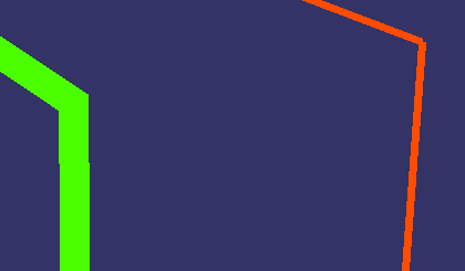
Some screenshots of the result lines. The red color line is drawn by using OpenGL default GL_LINE_STRIP, while the greenish line is drawn by using the shader program. Note how the connection between the anchor point does not look broken compared to the red line. For this case we turned on the multi-sampling.

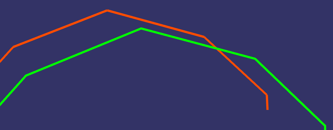
The demonstration of ability to produce much thicker lines. Not only the connection is smoother, but the line width can be set to any value. For this test we turned off the multi-sampling, just to demonstrate the visual difference.
Another, more general example of two lines drawn by different methods, side by side:
Codes
This tutorial had skipped many implementation details, that is why it is useful to refer to the source code for the fully functional example. Refer to the corresponding github repo. Note, the presented code includes some additional elements from 3D curves tutorial.
Leave a Comment